Rpi-shutdown-button: Difference between revisions
No edit summary |
(No difference)
|
Latest revision as of 07:54, 16 September 2020
A simple but very useful circuit to add to the raspberry pi's GPIO header is a Shutdown/Reset button with a feedback LED.
- pressing the button briefly triggers a reset
- pressing the button > 4 seconds triggers a shutdown
A status LED will indicate whether a reboot or shutdown has been initiated and will just blink once every 10 seconds to show that the computer is running and just doing its thing.
Schematic:
The current draw for each individual GPIO pin must stay below 16mA, and the total draw for the whole 3.3V power rail must stay below 50mA.
Using a 1k resistor for an LED we will have a current draw of less than 4mA.
Parts list:
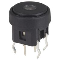
The pushbutton with LED illumination I used for this project was purchased from Jaycar.
- Part Number: SP0620 - SPST PCB Mount Tactile - Metallic Vertical with LED - Red
- 2x 1k Ohm 1/4W resistors
- 1x 3-pin .1" pitch IDC header
- 10cm ribbon cable (three wires)
- heat shrink (2mm diameter)
How to connect everything:
- strip a short bit of insulation on three wires of the ribbon cable from one end
- cut three small bits of heat shrink and shove over each of the three stripped wires
- solder the ends of the three stripped wires to the 3-pin IDC header
- cover the connections with heat shrink and apply heat to shrink them in place
- from the other end of the ribbon cable, cut the middle and one outer wire 5cm shorter
- trim the leads from the two resistor so that only a short bit of wire remains
- solder a resistor on each end of the two wires
- solder the cut-off 5cm pieces of wire to each of the resistor's other end
You should now have something like this:
- shove some short bits of heat shrink over the two resistors so the connections are insulated
- trim the ends of the two wires with resistors so that all wires are the same length
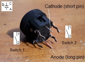
- familiarise yourself with the pinout of the pushbutton
- bend pin 1 from switch 1 so it touches the Cathode pin of the LED and solder these together
- solder the ribbon cable wire without resistors to the joint connection from the previous step (this will be the GND wire)
- solder the middle wire to the Anode (the long pin in the middle of the switch, this will be the LED wire)
- and lastly, solder the remaining wire to pin 2 of switch 1
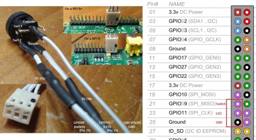
When all done, the connections to the switch should look something like in the below picture.
Use this image to connect the IDC header onto the Raspberry Pi connection header pins.
Python button-listener program:
- installing the software
install the python gpio library:
apt-get install python-rpi.gpio
Copy the python button-listener program to /usr/local/bin/shutdown-monitor.py
Then, set the permissions:
chmod 700 /usr/local/bin/shutdown-monitor.py
add to the command to the startup script:
vi /etc/rc.local
near the end of the script, but above the 'exit 0', enter the following line:
/usr/bin/python /usr/local/bin/shutdown-monitor.py > /dev/null 2>&1 &
The full code for the shutdown monitor:
# This script will wait for a button to be pressed and then shutdown
# the Raspberry Pi.

import time
from time import sleep
import RPi.GPIO as GPIO
import os

GPIO.setmode(GPIO.BOARD)

# Pin 21 will be input and will have its pull-up resistor (to 3V3) activated
# so we only need to connect a push button with a current limiting resistor to ground
GPIO.setup(21, GPIO.IN, pull_up_down = GPIO.PUD_UP)

# GPIO10 (on pin 23) will be our LED pin
GPIO.setup(23, GPIO.OUT)

GPIO.output(23, GPIO.HIGH)
sleep(1)
GPIO.output(23, GPIO.LOW)

int_active = 0


# ISR: if our button is pressed, we will have a falling edge on pin 21
# this will trigger this interrupt:
def Int_shutdown(channel):

        # button is pressed
        # possibly shutdown our Raspberry Pi

        global int_active

        # only react when there is no other shutdown process running

        if (int_active == 0):

                int_active = 1
                pressed = 1

                shutdown = 0

                # turn LED on
                GPIO.output(23, GPIO.HIGH)

                # count how long the button is pressed

                counter = 0

                while ( pressed == 1 ):

                        if ( GPIO.input(21) == False ):

                                # button is still pressed

                                counter = counter + 1

                                # break if we count beyond 20 (long-press is a shutdown)
                                if (counter >= 20):

                                        pressed = 0

                                else:

                                        sleep(0.2)


                        else:
                                # button has been released

                                pressed = 0

                # button has been released, dim LED, count cycles and determine action

                GPIO.output(23, GPIO.LOW)


                # count how long the button was pressed

                if (counter < 2):

                        # short press, do nothing
                        pressed = 0
                        int_active = 0

                else:
                        # longer press


                        if (counter < 20):

                                # medium length press, initiate system reboot

                                print("rebooting..")

                                # run the reboot command as a background process
                                os.system("shutdown -r 0&")

                                # blink fast until the system stops
                                blink = 1
                                while (blink > 0):

                                        sleep(0.15)
                                        GPIO.output(23, GPIO.HIGH)
                                        sleep(0.15)
                                        GPIO.output(23, GPIO.LOW)

                        else:

                                # long press, initiate system shutdown

                                print("shutting down..")

                                # run the shutdown command as a background process
                                os.system("shutdown -h 0&")

                                # blink slow until system stops
                                blink = 1
                                while (blink > 0):

                                        sleep(1)
                                        GPIO.output(23, GPIO.HIGH)
                                        sleep(1)
                                        GPIO.output(23, GPIO.LOW)


# Now we are programming pin 21 as an interrupt input
# it will react on a falling edge and call our interrupt routine "Int_shutdown"
GPIO.add_event_detect(21, GPIO.FALLING,  callback = Int_shutdown, bouncetime = 1000)

# blink once every couple of seconds while waiting for button to be pressed
while 1:

        time.sleep(10)

        # only blink when the button isn't pressed
        if ( GPIO.input(21) == True ):

                # only blink when there's no shutdown in progress
                if (int_active == 0):

                        GPIO.output(23, GPIO.HIGH)
                        sleep(0.1)
                        GPIO.output(23, GPIO.LOW)
                        sleep(0.1)

# That's all folks!


