TNC-Pi
APRS Terminal Node Controller for the Raspberry Pi
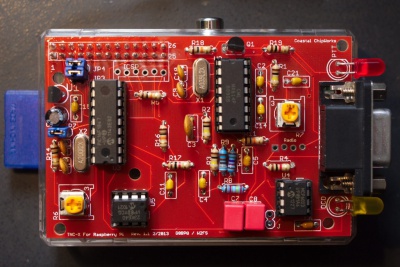
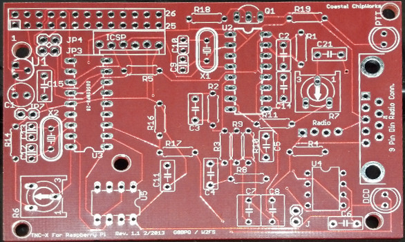
Circuit Board
Bell 202 chip: MX614P
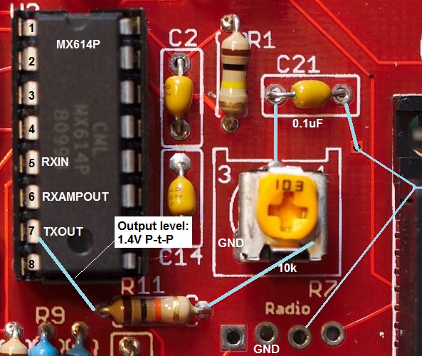
MX614P output levels
The audio output voltage seen on this chip is 1.4V peak-to-peak.
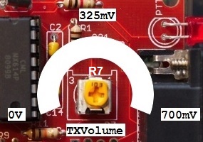
Output Volume
Trimpot R7 controls the output volume of the TNC-Pi to your radio. It is a single-gang pot and has a range from 0V (fully counter-clockwise) to about 700mV (fully clockwise)
The output signals are generated from the MX614P chip. The Audio_OUT on this chip is on pin 7. At any frequency, the output level on this pin is about 1.4V peak-to-peak. This is true for the 487Hz resting tone and the 1200Hz/2200Hz AFSK tones.
Input Volume
The input volume to the TNC was not found in any documentation but through experiment I found that a input voltage range between 170mV - 300mV was effective in successfully decoding APRS packets.
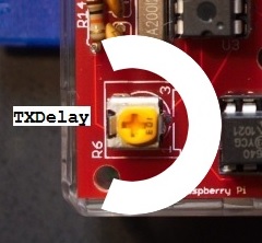
TXDelay
The time between PTT-on and actual transmit of data can be set with R6 which controls the TX-Delay. At this stage I have no further information on the range or effectiveness of this trimpot.
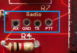
Radio Header
The 4-pin socket (header probably missing) labeled 'radio' is to get easy access to the Audio, GND and PTT lines.
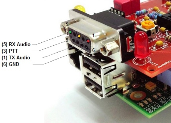
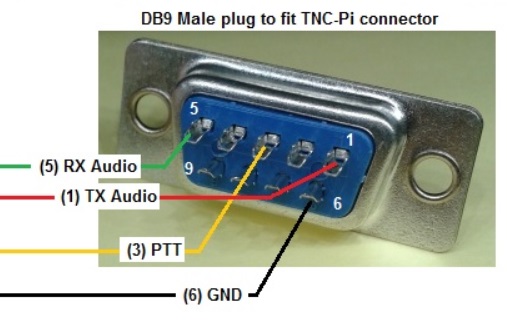
DB9 Pinout
The DB9 Female connector on the TNC-Pi board is used to interface RX Audio, TX Audio and PTT to the transceiver.
The pinout is as follows:
Looking at the solder side from a plug (DB9 Male) that fits into the above socket:
TX Audio is the audio coming out of the TNC when transmitting and will go to the radio to be transmitted.
RX Audio is the received audio coming out of the radio that is going to the TCN
PTT (push to talk) is done by the TNC-Pi by tying it to GND. This then puts most receivers into transmit.
