Mcu 0126-iambic-keyer
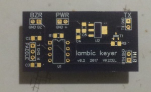
Sending Morse Code is a hobby that is still alive and well. This board uses an ATtiny45 or ATtiny85 microcontroller and can be used with an iambic keyer to send morse code. The code fits in a 4k ATtiny45 or the bigger 8k ATtiny85 Program Memory Flash.
I got the idea and code from Jack Welch: http://blog.templaro.com/?p=1315 (code here: https://github.com/dhakajack/jackyack/), who got his idea from Jan Lategahn, DK3LJ who has the original sources here: http://yack.sourceforge.net/
Brief overview of the main features:
- keying speed settable from 5 to 50wpm
- toggle paddle swap (if dit and dah paddles are wired incorrectly)
- chip-generated side tone to drive a small piezo transducer (adjustable pitch from 400-1500Hz or turned off completely)
- output TX switch-to-ground using low-power 2N7000 N-Channel FET (toggle inverted operation)
- send from 2x pre-recorded memory banks of 100 characters each
- 20-second tune-up constant tone
- supports Iambic-A, Iambic-B and Ultimatic modes
- random callsign trainer
- automatic Beacon mode
The ATtiny microcontroller runs internally on 8MHz, but has the CLKDIV8 flag set, which makes the program effectively run at 1MHz. These clock settings are factory default for a newly-purchased (empty) ATtiny85 chip so you don't need to set any additional Fuses when programming the code into the microcontroller.
Version 1
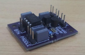
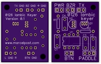
Initially I wanted to make the keyer on a small board with just through-hole components.
Ready to order from OSH Park: https://oshpark.com/shared_projects/EWy79eAF
Parts list:
- R1, R2: 10k (1/4W)
- C1: 100nF (MKT)
- C2, C3, C4: 10nF (MKT)
- U1: ATtiny45 or ATtiny85 (pre-programmed, internal oscillator @ 1MHz)
- U2: 78L05
- Q1: 2N7000
- header pins, .1" pitch (optional)
Gerbers: File:0126 Iambic Keyer gerbers.zip
Arduino Source code: File:0126 iambic keyer.zip
- Note: although the source code is in the Arduino .ino format, it is targeted for the ATtiny microcontroller. In order to program this code, you need to turn your Arduino (e.g. Dueamilanove or Uno) into an In-Circuit Serial Programmer (link: https://create.arduino.cc/projecthub/arjun/programming-attiny85-with-arduino-uno-afb829).
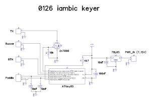
Schematic:
Version 2
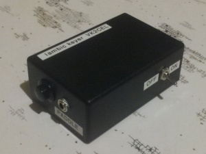
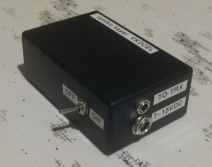
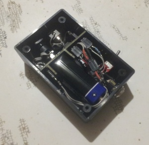
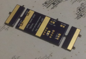
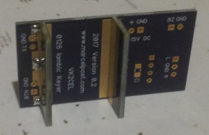
Once I sorted out some minor issues with the code and was confident that this was indeed a neat little project, I decided to try and fit it in a small plastic enclosure. The enclosure I chose had small internal rails, between which a circuit board can be held. I was hoping that the enclosure would be big enough inside to also hold a 9V battery, but this turned out to be a bit of a challenge. What I ended up doing was to make a pair of tabs at one end of the circuit board so it could hold the 9V battery in place. The result is what you see below. When the board is received, the end-tabs need to be snapped off and filed flush for a snug fit in the enclosure. The tabs are then soldered at 90 degree angles. Make sure to leave enough space around the battery for some additional insulation tape as the metal body of a 9V battery is NOT ground(!). I tried various small 9V snap-on tabs, but even the smallest ones are still too thick to fit everything inside the box. Therefore the only way this will work is to solder the power leads directly to the battery. Not ideal, but this way it all just fits.
(new schematic, not yet posted)
(gerber files, not yet posted)
(improved source code, not yet posted)
BOM
11x male header pins                      0.50   eBay
 6x female header pins receptacle         0.50   eBay
 1x DIP8 ATTiny85                         2.00   eBay
 2x 1206 10nF cer cap                     0.02   669-8410  RS
 1x 1206 100nF cer cap                    0.02   669-8408  RS
 2x 1206 1uF cer cap                      0.02   669-8414  RS
 2x 1206 10k res                          0.01   117-391   RS
 1x 1206 BSS138 N-Ch FET                  0.24   671-0324  RS
 1x SOT223-3 MCP1703-502E/DB LDO          0.91   669-4890  RS
 1x Piezo transducer 3500Hz               0.78   457-011   RS
 1x DIP8 IC Socket                        0.38   PI6500    Jaycar
 1x 1m 16-Way IDC ribbon cable            1.85   WM4502    Jaycar
 1x spdt sub-miniature toggle switch      2.95   ST0300    Jaycar
 1x small black SPST N/O momentary        3.95   SP0700    Jaycar
 1x DC Power 2.5mm Bulkhead connector     2.95   PS0524    Jaycar
 1x enclosure 130x68x44mm                 3.95   HB6013    Jaycar
 2x 3.5mm stereo chassis socket           1.35   PS0132    Jaycar
 1x Circuit Board 0126 Iambic Keyer       6.70   OSH Park
                                        ------
                                        $29.08 (AUD)  (2017 prices)
Sidetone
The keyer uses an internal oscillator for generating a sidetone. It is therefore recommended to use a piezo transducer in the design (do not use a buzzer that produces a tone when a dc voltage is applied). The keyer sidetone is useful for generating beeps when interacting with the keyer menu but it can also serve as audible feedback when the radio you're working with does not produce any tones when triggering the PTT line in CW mode. Enabling or disabling the keyer sidetone, as well as changing the pitch, can be set from the keyer menu.
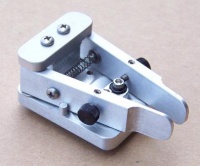
Here is a typical Morse paddle that can be used with this keyer.
http://americanmorse.com/dcp.htm
Getting started.
So you've soldered all the components, connected all the hardware and it's mounted in a box. Now what do you do?
The keyer has a few modes of operation. It can only be in one of these modes:
- iambic keyer mode
- Menu mode
- Callsign training mode
When the device is first powered up it will output '73' (on the internal speaker only) and start in iambic keyer mode, ready for paddle input.
If a paddle is connected you can send dits and dahs by tapping the left or the right paddle. In the menu you can configure common options such as:
- swapping the left and right paddle
- setting the internal speaker on or off during iambic keyer mode
- enabling or disabling the switched output (to key the radio)
- swap the switched output (key to GND or key to 5V)
- the tone of the CW from the internal speaker
- the speed of the CW
To enter the menu, press the command button once. It will send '?' ( . . - - . . ) to confirm it is in menu mode. If no paddle activity is sensed within 5 seconds it will time out, send 'SK' ( . . . - . - ) and return back into Iambic keyer mode.
While in menu mode, use the paddle to key in the letter of a corresponding menu option to activate it. The full list of options is shown below.
The following list of menu options is available:
@section usage Usage

After reset in default mode, the keyer operates as regular IAMBIC keyer in IAMBIC A at 15 WPM
(words per minute = 60 CPM), with 700 Hz side tone. By default, the transmitter keying signal is
positive.


@subsection speed Speed Change

Speed can be changed by pressing and holding the command key while operating the DIT and DAH paddles.
DIT reduces speed while DAH increases speed. The keyer plays an alternating sequence of dit and dah while
changing speed without keying the transmitter.


@subsection cmode Command mode

Pressing the command button without changing speed will switch the keyer into command mode. This will be
confirmed with the '?' character. Another press of the same button takes the keyer back into regular
keyer mode and will be confirmed by the 'SK' prosign.

During command mode the transceiver is never keyed and sidetone is always activated. Further
functions can be accessed by keying one-letter commands as listed below.


@subsubsection Version V - Version

The keyer responds with the current keyer software version number


@subsubsection pitch P - Pitch

Allows modifying the sidetone pitch to a higher or lower level. A sequence of dits will be played
and the pitch can be modified with the dit and dah paddles. If no paddle is touched for 5 seconds,
the acknowledgment signal 'R' is sounded and the mode terminates, leaving the user in command mode.


@subsubsection reset R - Reset

All settings are returned to their default values except for the stored messages in the message buffers.
Restored settings include speed and pitch, Paddle Swap, TX level inversion, sidetone and TX keyer settings.


@subsubsection tune U - Tune mode

The transceiver is keyed for a duration of 20 seconds for tuning purposes. Tuning mode is aborted once either
DIT or DAH paddles are touched or the control key is pressed.


@subsubsection ia A - IAMBIC A

Keyer sets IAMBIC A as permanent keying mode. An 'R' is sounded to acknowledge the request.


@subsubsection ib B - IAMBIC B

Keyer sets IAMBIC B as permanent keying mode. An 'R' is sounded to acknowledge the request.


@subsubsection ultimatic L - Ultimatic

Sets the keyer into ULTIMATIC mode. In Ultimatic mode always the last paddle to be touched is repeated indefinitely
when paddles are squeezed


@subsubsection dahprio D - DAH priority mode. In squeezed state a sequence of DAHs is sent.

Some of the first generation keyers exhibited this behaviour so the chip can simulate that


@subsubsection swap X - Paddle swapping

DIT and DAH paddles are swapped. An 'R' is sounded to acknowledge the request.


@subsubsection side S - Sidetone toggle

The built-in sidetone generator setting is toggled (ON -> OFF or OFF -> ON). NOTE: This setting is only of relevance
for regular keying mode. Sidetone is always on in command mode. An 'R' is sounded to acknowledge the request.


@subsubsection txtog K - TX Keying toggle

Toggles the setting of the TX keyer output. In default state the keyer switches the output line when it is in keyer mode.
Toggling this setting enables or disables that function. NOTE: Keying is always off in Command mode. An 'R' is sounded to
acknowledge the request.


@subsubsection farnsworth Z - Set Farnsworth pause

Allows setting of an extended inter-character pause in all sending modes, which makes fast keying easier to understand.
Note that this of course only influences RECEPTION, not TRANSMISSION. If you desire farnsworth mode in transmission, please
manually pause during characters.


@subsubsection lvtog I - TX level inverter toggle

This function toggles wether the "active" level on the keyer output is VCC or GND. The default is VCC. This setting
is dependent on the attached keying circuit. An 'R' is sounded to acknowledge the request.


@subsubsection query W - Query current WPM speed

Keyer responds with current keying speed in WPM.


@subsubsection msgrec 1 and 2 - Record internal messages 1 or 2

The keyer immediately responds with "1" or "2" after which a message up to 100 characters can be keyed at current WPM speed.
After 5 seconds of inactivity the message is played back once and then stored in EEPROM. Choosing "1" or "2" but not keying
a new message deletes the chosen message buffer content.


@subsubsection msgplay E and T - Play back internal messages 1 or 2

The stored messages 1 or 2 are played back with keying enabled (if configured). A press of the command key immediately
returns the keyer to keyer mode so a QSO can be started.


@subsubsection beacon N - Automatic Beacon

The keyer responds with 'N' after which a number between 0 and 9999 can be keyed. After a 5 second timeout the keyer
responds by repeating the number and 'R'. Once the keyer returns to keyer mode, the content of message buffer 2 is
repeated in intervals of n seconds. The setting is preserved in EEPROM so the chip can be used as a fox hunt keyer.

Returning to command mode and entering an interval of 0 (or none at all) stops beacon mode.


@subsubsection lock 0 - Lock configuration

The 0 command locks or unlocks the main configuration items but not speed, pitch and playback functions.


@subsubsection trainer C - Callsign trainer

The keyer plays a generated callsign (sidetone only) and the user must repeat it. If it was repeated correctly, 'R' is
played and the next callsign is given. If a mistake was sensed, the error prosign (8 dits) is sounded and
the current callsign is repeated again for the user to try once more. If nothing is keyed for 10 seconds, the keyer returns
to command mode.
