Mcu 0051-lcd-i2c-board
| 0051-lcd-i2c-board | |
 |
|
| 0051-top-with-lcd | |
| Project Details | |
| Author | Marcel Post |
|---|---|
| MCU | AVR ATtiny85 |
| Initial Release | August 2011 |
| Last Modified | January 2013 |
| PCB Layers | 2 |
| Status | finished |
| Category: | Electronics |
The LCD Board with I2C comms is a basic display board that accepts incoming data over I2C. It can be hooked up to a low-speed I2C network and its ID# can be set using a pushbutton.
Description
After obtaining enough information on how to drive a 2 x 16 LCD unit with only three wires (by using a serial shift register) this board was my first attempt to produce something workable.
Timeline
- 2012-01-20 added major release of software version 1.0. This code is working fine.
- 2012-01-03 PCB's arrived and I've built up two boards.
- 2011-11-27 Ordered 2x PCB's with BatchPCB. Only after the boards have arrived, built up and tested I will post relevant firmware on this page. Until then!
- 2011 November - Finished schematic and designs
- 2011 September - Started designing a custom circuit board using the Diptrace software
- 2011 June - Prototype working with successful communication using an Arduino Duemilanove as the I2C master.
Schematic
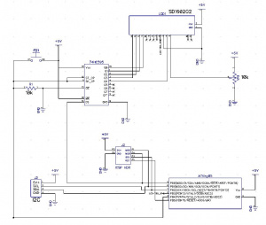
View schematic as pdf (Oct 2011) File:0051-sch-1.0.pdf
Circuit Board
Nov 2011 - Finished design, now it's waiting for pcb manufacturing.
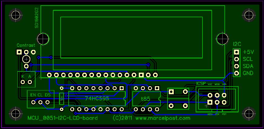
Latest design (November 2011)
Gerbers: File:0051-gerbers.zip
Other boards I'm currently designing: Pending_PCB_manufacturing
Software
Diptrace files (schematic and PCB): File:0051-I2C-LCD-board-v1.0.zip
Firmware:
v0.04 File:0051-lcd-i2c-v0.04.zip Released: 2 January 2014
v0.03 File:0051-firmware v0.03.zip Released: 1 April 2013
NOTE:
Be aware that I2C does not need a specific operating frquency. The code for this chip should be running on 8MHz in order with other I2C devices, but it may run on lower frequencies as well. I haven't tested this yet. So be sure to set the lower fuse byte to 0xE2 to disable CLKDIV8 and to make the chip run on 8MHz. Check the PROG.BAT or prog file for the proper settings.
Release Notes
- The pushbutton sets the internal I2C id. To use this, hold down the push button and then apply a voltage source to power up the board. With the button pressed the display will show black characters on the top row of the display. After 5 seconds, release the button and the board will go into setup mode. The display should show the current I2C id. The I2C protocol will be able to address a maximum of 127 devices on the bus. Pressing the button will cycle through these values. Press and hold the button for about 5 seconds to store the new ID into eeprom.
- When assembling the board I would recommend not to install the push button until you have confirmed that the display is showing activity. I had a case where I assembled the board and all I could see was a dark top half of the screen and nothing seemed to work. It turned out that I didn't install the push button properly. It made a connection between the top two pins even when the button was not pressed. This basically means that the board will try to go into setup mode but never gets further because the button is not released properly.
- The serial shift register chip I use is the M74HC595B1 from ST.
- When assembly has been completed and the ATtiny84 has been flashed with the proper firmware the board is ready to use. When powered on it will show a brief message 'I2C LCD Module' and on the second row 'Listening..'. The screen is cleared and it will sit there until there's something to display.
- (bug?) There may be a bug with this firmware that can cause the display not to work properly. I need to test this further but my concern is this: brand new microcontrollers have their EEPROM empty. This could mean '0x00' or '0xFF' or maybe even something else. The v1.0 firmware currently does not detect an out of range value and may cause the read-eeprom-value to fail. Whether this affects further operation of the board is unknown as I don't have any brand new chips to test with. If this is a bug it can be remedied fairly easily by following these steps:
 1.  change the source code and add a line that will write a value (e.g. decimal 61) to eeprom
 2.  compile the code and write to the chip using the ISP header (or use an external programmer)
 3.  power up the board and enter the setup mode to confirm that the ID has been set
 4.  change the source code to remove the line that was added in step 1
 5.  compile the code and write to the chip
- The software was developed using an Arduino as I2C master running at 16MHz. The ATtiny can keep up with this speed due to clock stretching. Howerver, to speed up communications it would be worthwile to set the clock speed of the ATtiny as high as possible. The ATiny85 can run at 1, 8 or 16MHz. Use the following fuse bytes to set the clock:
| Speed | Low Fuse Byte | High Fuse Byte |
| 1MHz | 0x62 | 0xDF |
| 8MHz | 0xE2 | 0xDF |
| 16MHz | 0xC1 | 0xDF |
Command line example using avrdude:
avrdude -c %PGM_PROTO% -P %PORT% -p %PGM_DEVICE% -U flash:w:%PROJECT%.hex -U lfuse:w:0xE2:m
- The display board will assume end of transmission after a timeout. This can be set in the code and is currently set to 5 seconds.
- As per the I2C protocol the device supports giving an acknowledge by holding down SDA line.
- The board does not provide I2C bus pull-up resistors. You will have to add these to your project. (arduino's do have pull up resistors on the I2C bus)
Command reference:
To send data to the I2C LCD board you will need to use I2C and address it to the device's I2C id.
Use ASCII values to send individual characters to the display (e.g. '65' is 'A').
| ASCII | Description |
| 12 | Clear Display |
| 10 | Enable Character Positioning (must be followed by row and column, see below) |
| 32-126 | Standard ASCII Characters |
Character positioning
Use the '10' special command to position a character on the display.
Example:
 send: 10  (enables character positioning)
 send:  1  (go to first row)
 send: 12  (go to 12th column)
 send: 66  (send the letter 'B')
Example code for arduino:
// put random characters on random places on the display

#include <Wire.h>
int device_id=61;

void welcome_text()
{
  Wire.beginTransmission(device_id); // define device nr to transmit to
  Wire.send(12);                     // clear the display
  Wire.send("--- I2C Demo ---");     // welcome text line 1
  Wire.endTransmission();            // stop transmitting

  delay(3000);

  Wire.beginTransmission(device_id); // define device nr to transmit to
  Wire.send(12);                     // clear the display
  Wire.endTransmission();            // stop transmitting

}

void setup()
{
  Wire.begin();                      // join i2c bus (address optional for master)
  Wire.beginTransmission(device_id); // define device nr to transmit to
  Wire.send(12);                     // clear the display
  Wire.endTransmission();            // stop transmitting
}

void loop()
{

  byte x,y,z,letter;

  welcome_text();

  for (z=255; z > 10; z=z-10)
  {

    letter=random(65,91);
    y=random(1,3);
    x=random(1,17);

    Wire.beginTransmission(device_id); // define device nr to transmit to
    Wire.send(10);              // enable character positioning
    Wire.send(y);               // row:
    Wire.send(x);               // col:
    Wire.send(letter);          // place a letter
    Wire.endTransmission();     // stop transmitting

    delay(z*2);

    Wire.beginTransmission(device_id); // define device nr to transmit to
    Wire.send(10);              // enable character positioning
    Wire.send(y);               // row:
    Wire.send(x);               // col:
    Wire.send(" ");             // overwrite the letter with space
    Wire.endTransmission();     // stop transmitting

  }

}
Gallery
Below you can see the display is connected to an Arduino Duemilanove over I2C. The Arduino is sending out some text and the display board puts it on the screen.
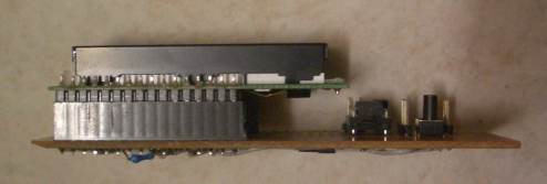
Side-view of the board with the LCD unit mounted on top. The LCD unit used is the one Jaycar sells in Australia. Model number is SD1602.
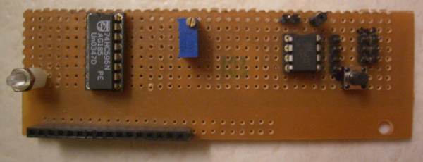
Top-view of the board without the LCD unit. Here you can clearly see the serial shift register chip I used to save on data pins to the mcu.
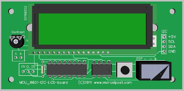
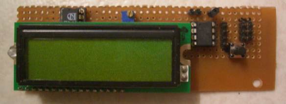
Top-view of the board with the LCD unit mounted.
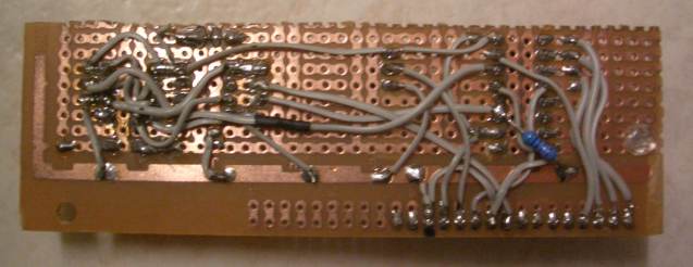
Working prototype (June 2011)
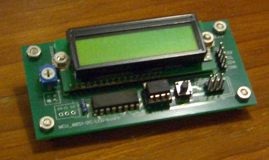
Custom pcb for this project
Here is a movie of I2C in action. I slowed down the sending of signals on an I2C master and enabled the display of control characters on the LCD board.
<mediaplayer useSWF=false autoplay=false image=/swf/img/lcd-i2c-demo.jpg>/swf/i2c-demo.flv</mediaplayer>
An explanation of the codes on the display:
S = Start sequence detected
M =
L =
A = LCD generates Acknowledge
L =
P = Stop sequence detected
Purchasing a board
(all out of stock!)
