PCA9535 IO expansion port
The PCA9535 and PCA9535C are 24-pin CMOS devices that provide 16 bits of General Purpose parallel Input/Output (GPIO) expansion for I2C-bus/SMBus applications.
Example schematic and code for Arduino Duemilanove and UNO (and possibly others).
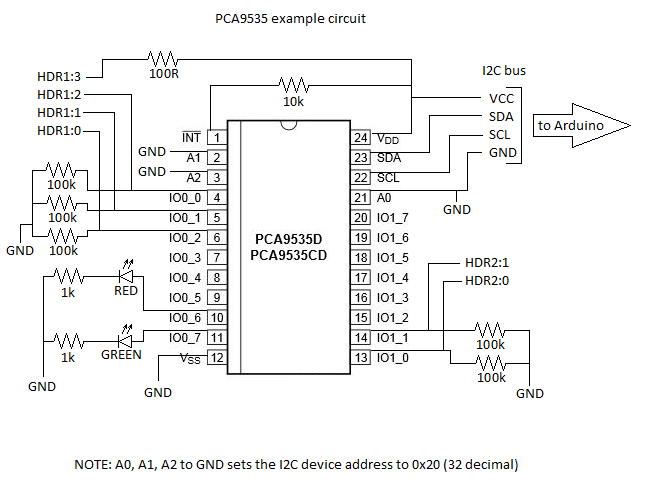
Schematic
Brief explanation:
- The Arduino provides 5V to the port expander and LEDs through the I2C header
- The Arduino I2C pins are on Analog In port 4(SDA) and 5(SCL) (not shown)
- The INT line is held high to VCC with a 10k pullup resistor
- A 100R current limiting resistor is in line to HDR1:3 to provide +5V for a small probe lead
- The I2C address is set to 0x20 (decimal 32) by pulling A0, A1 and A2 low to ground
- HDR1:0 to 2 and the two LEDs are all on channel 0
- HDR2:0 to 1 are all on channel 1
- 100k pulldown resistors to ground are placed on all input pins
- 4k7 pullup resistors to +5V for the I2C lines are added on the Arduino side of the I2C bus (not shown)
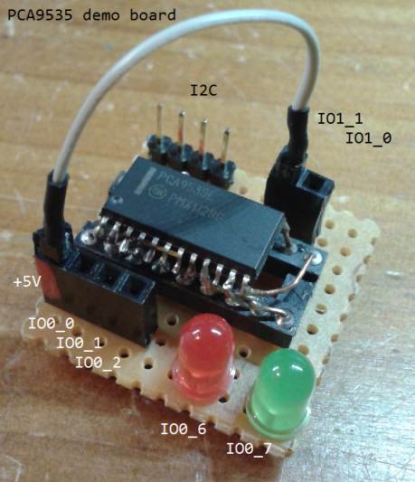
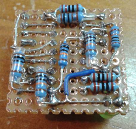
Demo Circuit Board
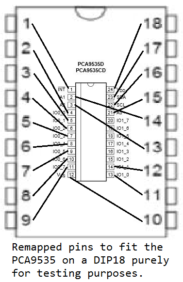
In order to work with the SOIC package I decided to re-route some pins and not break out all ports so I could mount it on a DIP18 socket.
The re-mapped pins and the completed demo board are shown below:
Code
/*

  Arduino demo code for the PCA9535 I2C port expander.
  Compatible with Arduino IDE version 1.0.5
  Last modified: 26 January 2014

*/

#include <Wire.h>

//  I2C 9535 device address is 0 1 0 0   0 0 0 (0x20, or 0d32)
#define PCA9535_ADDR 32

int ch0=0;
int ch1=0;

void setup()
{

  Wire.begin();

  // setup channel 0 and 1
  Wire.beginTransmission(PCA9535_ADDR);
  Wire.write(6); // configure port 0 registers
  Wire.write(B00111111); // set bit 6+7 as output, the rest input
  Wire.write(B11111111); // set all as input
  Wire.endTransmission();

}


void loop()
{


  PCA_ReadBytes(); // read the values of channel 0 and 1


  // channel 0

  if (bitRead(ch0,0))
  {
    // bit 0 of channel 0 is set high
    blinkLed(0,1);  // blink one time
  }
  if (bitRead(ch0,1))
  {
    // bit 1 of channel 0 is set high
    blinkLed(0,2);  // blink two times
  }
  if (bitRead(ch0,2))
  {
    // bit 2 of channel 0 is set high
    blinkLed(0,3);  // blink three times
  }


  // channel 1

  if (bitRead(ch1,0))
  {
    // bit 0 of channel 0 is set high
    blinkLed(1,1);  // blink one time
  }
  if (bitRead(ch1,1))
  {
    // bit 1 of channel 0 is set high
    blinkLed(1,2);  // blink two times
  }


  delay(1000);
  delay(1000);


}


void blinkLed(int lednr, int times)
{
  if (lednr==0)
  {
    lednr=B01000000; // bit 6 goes to the RED led
  } else {
    lednr=B10000000; // bit 7 goes to the GREEN led
  }

  while (times>0)
  {

    // turn led on I/O 0, pin 6 or 7
    Wire.beginTransmission(PCA9535_ADDR);
    Wire.write(2); // select IO channel 0
    Wire.write(lednr); // turn on port on bit 6 or 7
    Wire.endTransmission();
    delay(100);
    all_off();
    delay(300);

    times--;

  }
}


void all_off()
{
    // turn off all outputs
    Wire.beginTransmission(PCA9535_ADDR);
    Wire.write(2); // select IO channel 0 output registers
    Wire.write(B00000000); // turn off all ports on channel 0
    Wire.endTransmission();
}


void PCA_ReadBytes()
{
  // reads the input registers of the PCA9535 device

  // read channel 0 first
  Wire.beginTransmission(PCA9535_ADDR);
  Wire.write(0); // we want to read channel 0 first
  Wire.endTransmission();
  Wire.requestFrom(PCA9535_ADDR,2); // read two bytes
  if(Wire.available())
  {
    ch0 = Wire.read(); // read channel 0
    ch1 = Wire.read(); // read other channel (channel 1)
  }
  Wire.endTransmission();
}
Download the above code as a .zip file here.
Arduino source code: File:PCA9535 Arduino demo.zip
Something on I2C bus speed for the Arduino
The following blurb on I2C speeds is not relevant in order to get the PCA9535 to work, because it works just fine with the standard Arduino. However, for debugging purposes it is very handy to know that the I2C bus speed can be modified. I didn't have a better place to put this info, so here it is..
The default prescaler is 1, and the default value for TWBR (on the Uno etc.) is 72. Thus:
freq = 16000000 / (16 + 144) = 100000
 TWBR   prescaler   Frequency

 12       1       400   kHz  (the maximum supported frequency)
 32       1       200   kHz
 72       1       100   kHz  (the default)
152       1        50   kHz
 78       4        25   kHz
158       4        12.5 kHz
To set the prescaler to 4 you need to set the bit TWPS0 in TWSR, so for example to have a clock of 12.5 kHz:
  Wire.begin ();
  TWBR = 158;
  TWSR |= _BV (TWPS0);
The internal buffer used for I2C communications is 32 bytes. That means you can transfer a maximum of 32 bytes in one transaction.
It also isn't particularly clear, but the functions Wire.beginTransmission and Wire.write don't actually send anything. They simply prepare an internal buffer (with a maximum length of 32 bytes) for the transmission. This is so that the hardware can then clock out the data at a high rate. For example:
  Wire.beginTransmission (SLAVE_ADDRESS);  // prepare internal buffer
  Wire.write ("hello world");              // put data into buffer
  byte result = Wire.endTransmission ();   // transmission occurs here


