Mcu 0062-LCD-48x84-RC-Enclosure-top-pcb
| LCD pcb | |
 |
|
| 48x84 LCD Board | |
| Project Details | |
| Author | Marcel Post |
|---|---|
| MCU | (none) |
| Initial Release | 11-2011 |
| Last Modified | 11-2011 |
| PCB Layers | 2 |
| Status | design complete |
| Category: | Electronics |
Multi-purpose top PCB for a Remote Control enclosure that has circuitry, holes, pushbuttons and connectors for a Nokia 3310/5510 48x84 pixels LCD.
Description
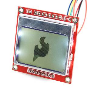
This is a generic board with for LCD functionality to be mounted inside a plastic project box sold as a 'Remote Control' enclosure. The enclosure has mounting holes top and bottom and this pcb is to be mounted on the top half of the enclosure. Due to the basic functionality of this design it is an ideal addition to other projects requiring some kind of graphical interface. The LCD to be mounted on top of this PCB is the Nokia 3310/5510 breakout board that Sparkfun sells for about $10. There is room to mount three pushbuttons on the board and there are pads available to insert pull-down-to-ground resistors. The idea is to have the mcu pushbutton pins configured as inputs and pulled down to ground with the resistors on this board. When a button is pushed VCC sends the voltage to the input pin and a press is detected.
Timeline
- 2011-11-27 Ordered 2x PCB's with BatchPCB. Only after the boards have arrived, built up and tested I will post relevant firmware on this page. Until then!
- November 2011 Finished designing the pcb and updating this webpage with relevant artwork.
- November 2011 Finished writing the code to get the Nokia board working with an Atmel ATtiny84 mcu.
Schematic
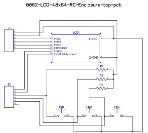
The schematic is pretty simple. Visible are the pushbuttons with their individual pull-down resistors. They share VCC with the LCD.
View schematic as pdf (Nov 2011) File:0062-sch-v1.0.pdf
Circuit Board
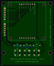
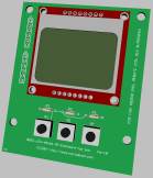
This is the final preview of the pcb before manufacturing.
I have placed the jumpers on the side so that an underlying project board can easily connect to the LCD board using ribbon cable.
Top view of the display board in a semi-transparent way (groundplane visible)
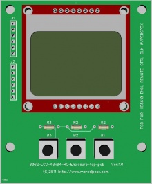
Here is a 3d view of the board with the Nokia LCD fitted on top.
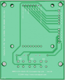
Top and bottom view of the display board.
Software
Latest source code: (not appliccable)
Gerber files: File:0062-gerbers-v1.0.zip
Release Notes
Other boards I'm currently designing: Pending_PCB_manufacturing
Gallery
The original Sparkfun breakout board for the Nokia 3310 monochrome LCD.
External Links
http://www.sparkfun.com/products/10168
