Mcu 0050-handheld-tempsensor
| 0050-ds1820-tempsensor | |
 |
|
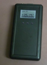
| prototype | |
| Project Details | |
| Author | Marcel Post |
|---|---|
| MCU | ATtiny85 |
| Initial Release | Month Year |
| Last Modified | Month Year |
| PCB Layers | 2 |
| Status | in development |
| Category: | Electronics |
DS18S20 based Handheld Temperature sensor, for use with Mcu 0062-LCD-48x84-RC-Enclosure-top-pcb.
Description
Years ago I started a similar project, creating a hand-held temperature sensor using a PIC16F84 with four 7-segment displays. The original project still works very well but I would like some more features added, such as:
- better display (using the Nokia 48x84 monochrome LCD instead of four 7-segment displays)
- support for multiple DS1820 sensors using the one-wire protocol
- better accuracy (PIC-based device has half-degree accuracy, this device will have 2 decimals accuracy)
- optimising the code to get the most out of battery life (current PIC-based device does 2.7mA @ 3.09V, early tests show I can get down to 1.95mA, that's about 25% better)
- store values (data logging) using EEPROM over i2c and graphical display of past values and trends
- setting thresholds and signaling over and under-temperature events (for use as a thermostat)
- wireless transmission of (stored) values
One of my preferences for this project is to design custom PCB's that fits inside the Jaycar HB5610 Remote Control Enclosure.
The code for this project also formed the basis for mcu_0055-rs232-tempsensor.
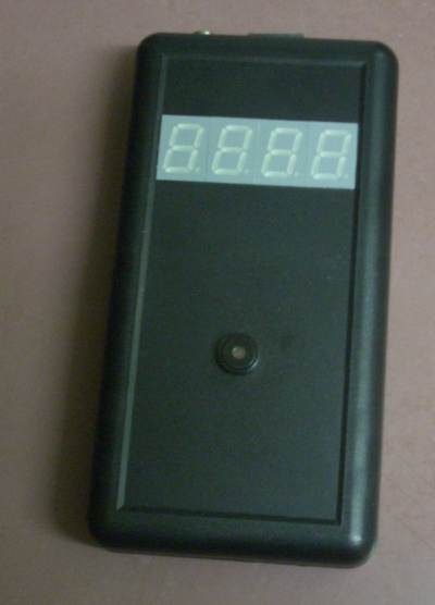
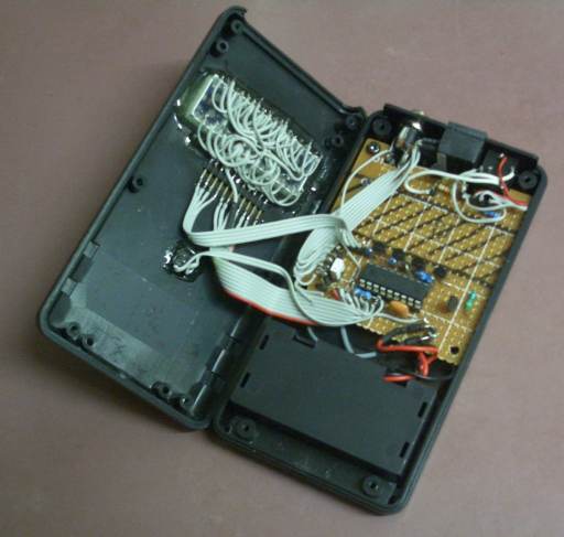
The original project, based on the PIC16F84 using four 7-segment displays and running off two 1.5V AA batteries.
Timeline
- 2011-11-27 Ordered 1x PCB with BatchPCB. Only after the boards have arrived, built up and tested I will post relevant firmware on this page. Until then!
- 2011-11-18 Decided to make the top-half a stand-alone project for use with other projects if required. See Mcu 0062-LCD-48x84-RC-Enclosure-top-pcb.
- 2011-11-13 Practically finalised the design for the top-half pcb with the LCD and buttons
- 2011-11-03 Did up a design in diptrace for the RC Enclosure internals.
- 2011-10-01 Got the DS1820 one-wire code working on ATtiny85
Schematic
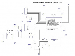
This project is designed to fit in the enclosure's bottom half (with battery compartment).
View schematic as pdf (Nov 2011) File:0050-sch-v1.0.pdf
Circuit Board
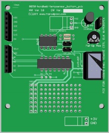
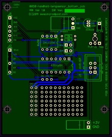
Bottom pcb with the mcu, eeprom, isp header and the on-board temperature sensor. Please note that these are not yet finished designs but I expect to be 90% there. One of the things I haven't tested yet is the clearance between the top and bottom pcb's once fitted inside the enclosure and see if it clashes with certain components.
The pcb for the bottom-half of the enclosure.
see-through model of the bottom pcb.
Gerbers: File:0050-gerbers-v1.0.zip
Software
Latest source code: File:Mcu 0050 tempsensor 20110601.tar.gz
Release Notes
Gallery
External Links
http://www.jaycar.com.au/productView.asp?ID=HB5610&form=CAT2&SUBCATID=986#1
