5W T-match Antenna Tuner
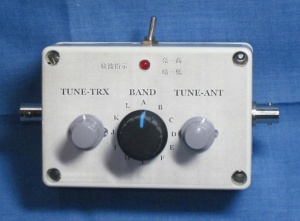
eBay lists this product as the "QRP 1-30MHz Manual Days Antenna Tuner" (手動天調套件). The 'Days' is probably due to an incorrect translation for DIY (do-it-yourself). In 2017 I purchased this kit off eBay for just under AU$16 and free delivery.
Specifications:
- Frequency range: 1 - 30MHz
- Impedance matching range: 40 - 300 Ohms
- Maximum RF Power: 5W
- Network type: T-Network
- Built-in SWR indicator LED (Dan Tayloe)
- Insertion loss: ?? dB
- Input impedance: 50 Ohms
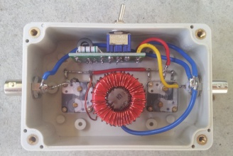
Completed kit build
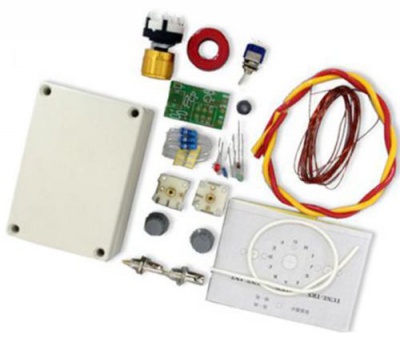
All the parts inside the kit
I got this kit with about 2.76m of enameled copper wire for the two toroids. For the bigger 12-tapped toroid windings I used 1.71m. Definitely more than enough was provided by the kit.
Toroid type and dimensions:
T106-2
- outer diameter: 26.9mm
- inner diameter: 14.5mm
- thickness: 11.1mm
- material: Carbonyl
- colour: red with one side clear (grey)
- characteristics: 250 KHz - 10 MHz
FT37-43
- outer diameter: 9.5mm
- inner diameter: 4.75mm
- thickness: 3.3mm
- material: Type 43
- color: unpainted (grey)
- characteristics: Wideband Transformers up to 50 MHz
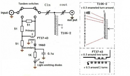
Schematic:
The silkscreen for the small PCB has an error in the labels for T1. The schematic (which is correct) shows that the primary (IN) winding should have 2 turns and the secondary (OUT) winding should have 5 turns. The PCB however has been shipped with these labels swapped. For clarity I have added the correct labels for T1 on the picture below.
NOTES
- There are several issues with this kit that may not be obvious at first glance. First of all, the kit does not come with a schematic. You'll either have to use the schematics on this page or find the appropriate schematic off Google elsewhere.
- some have reported that the screws that come with the variable capacitors may be too long and can cut into the dielectric material inside the variable capacitor housing.
- perhaps on earlier revisions the capacitor on the pcb was shown to be across the secondary winding, this is incorrect. My board had 'V2.0' printed on it and I could not see a fault in the tracks for the capacitor (check the schematic, it is correct and shows the capacitor going to ground after the diode).
- The windings on the big toroid may be a squeeze-fit to go on the 12-position selector switch. Just make sure to keep a longer lead (about 10cm) on the 10-windings side to connect it to the variable capacitors. The 12 positions all connect to tapped wires (except the beginning-10-turn-lead and the centre pin on the rotary switch is connected with an insulated wire to ground. This wire can either go through the toroid or alongside the switch body.
- when pressing the knob on the 12-position switch, also use a block or rod that provides pressure support from the back of the switch. When I had the rotary switch already mounted on the enclosure and attempted to push the knob on, the pressure was enough to undo all four clamps and separated the top and bottom half of the switch. Although not disastrous, I noticed that when I put the switch halves back together, the resistance to move from one position to the next was very low.
- the self-adhesive stencils are not exactly in the middle. Especially the top one was off by several mm's so that when I wanted to fit one of the tuning capacitors I noticed that one of the internal screw posts was in the way.
Tuning best practice
There are usually an infinite number of combinations that allows a T-Network tuner to match impedances. However, there are some combinations of L and C that allow for better power transfer (and minimise losses) than others. Ideally we want to use the lowest amount of inductance required as the windings on the toroid are more lossy than the capacitors. Here is a recommended tuning best practice for a tapped-inductor T-network tuner:
- Set the transmitter-side input Capacitor (Cin) and the antenna-side output Capacitor both to mid-scale.
- Select an inductance switch position and rotate Cout to detect a slight SWR dip.
- Set the inductance switch to another position if you didn't detect a dip. Only use Cout to check for a dip.
- When you find a dip, adjust Cin for minimum SWR.
- Move Cout slightly in one direction and use Cin to find minium SWR again.
- If the SWR is lower than it was, continue to move Cout in the same direction until lowest SWR has been reached.
- If the SWR is higher than it was, move Cout in the other direction and repeat above steps until lowest SWR has been reached.
- If an SWR dip can be found on two inductance settings, choose the lower inductance to get the larger output capacitance.
(From 'Getting the most out of your T-Network antenna tuner' by Andrew S. Griffith, W4ULD, QST Jan 1995)


